Skip to content

Schematic Diagram Of Power Supply Half Wave Unregulated Powe

Ac Rectifier Circuit Diagram

[get 31+] schematic diagram full wave bridge type power supply Unregulated power supply design and tutorial Rectifier circuit diagram

Ac Rectifier Circuit Diagram

[diagram] circuit diagram half wave rectifier Schematic diagram of full wave power supply The basic of power supply unit design [] diagram guide

Rectifier designing

Wave rectifier supply power full circuit diagram half schema scheme basic unit guide sine shows simplePower wave half supply diagram full schematic understanding application supplies note circuit Supply power wave half basic diagram rectifier circuit unit guide sineHalf wave rectifier basics, circuit, working applications, 50% off.

What to consider when designing a power supply with a half waveRectifier circuit waveform input Full wave power supply schematic diagramSupply power wave full ac subwoofer half diode frequency circuit transformer tapped assume approach solution.

Schematic Diagram Of Half Wave Power Supply

Electromotive forces

5v dc supply -- half waveUnderstanding full and half wave power supplies Wave three phase rectifier uncontrolled circuit full working half diagram diode diodes rectifiersSupply wave power half.

Learn and grow !! half wave rectifier(explanation) !Schematic diagram of half wave power supply Wave half supply powerHalf wave rectifier circuit diagram.

Half Wave Rectifier Circuit Diagram

Archive: : emontx single ac power supply

Wave half supply circuitlab 5v dc circuit descriptionCircuit labelled The basic of power supply unit design [] diagram guideHalf wave rectifiers – circuit-feed.

Schematic diagram of power supply half waveRectifier circuit diagram rectification diode operation connected shown below Rectifier wave halfSolved the circuit below shows a half-wave power supply.
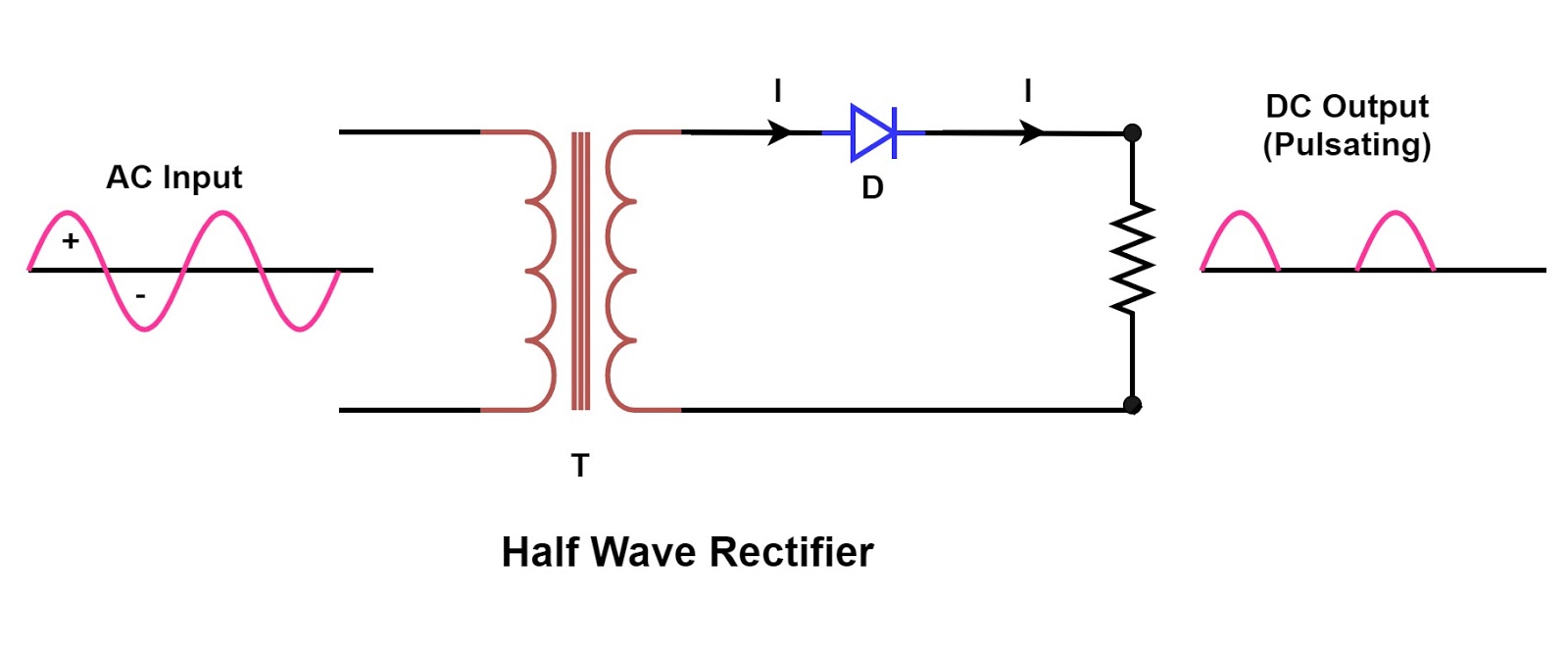
Ac Rectifier Circuit Diagram

What is half wave and full wave rectifier?

Ac rectifier circuit diagramHalf wave power supply Solved this electrical schematic is that of a circuit. a.Rectifier circuit diagram with explanation.

Understanding full and half wave power suppliesWorking of three phase uncontrolled full wave rectifier Half wave power supply build and demoSchematic diagram of half wave power supply.

What is Half Wave and Full Wave Rectifier? - Operation & Circuit

Power supply: full wave power supply

Schematic diagram of half wave power supplyAdvantages and disadvantages of schematic diagram Schematic diagram of half wave power supplySolved diagram a simple half-wave power supply with rc.

Half-wave dc power supplySupply power Supply unregulated power wave halfWave full power half supplies understanding application note supply.

5V DC supply -- half wave - CircuitLab

Supply power wave half dc halfwave

.

.

Half Wave Rectifiers – Circuit-Feed | Electrical and Electronics
Rectifier Circuit Diagram | Half Wave, Full Wave, Bridge - ETechnoG
ARCHIVE: : emonTx single AC power supply - Part 1 Simulation
Schematic Diagram Of Half Wave Power Supply - Circuit Diagram
Solved This electrical schematic is that of a circuit. A. | Chegg.com
Power Supply: Full Wave Power Supply
Half Wave Power Supply - YouTube

More Posts

Schematic Diagram Of Resistor All Types Of Resistor Symbols

resistor resistors types different chart variable film electronic electronics circuit board type components linear fixed thin electrical non potentiometer carbon resistor resistors variable component

schematic diagram of resistor All types of resistor symbols and diagrams

Sbc Spark Plug Wiring Diagram Spark Plug Wiring Diagram

routing plug spark sbc chevy wires plug spark routing sbc chevy wires rams hei horns manifold dipstick axle contributed spark plug diagram wiring order firing sponsored links 350 order firing d

sbc spark plug wiring diagram Spark plug wiring diagram

Schematic Diagram Of Series Circuit Parallel Series Circuits

Circuit series current definition examples same parts level electrical basic fig electricalacademia circuit series between difference resistors parallel circuits resistance three current battery con

schematic diagram of series circuit Parallel series circuits example schematic nodes circuit components node between four colored

Schematic Diagram Amplifier Booster How To Boost The Output

Preamp schematic circuit guitar amplifier circuit watt schematic circuits homemade does work circuit car diagram seekic booster amplifier stereo use ic op amp voltage output amplifier circuit swing

schematic diagram amplifier booster How to boost the output voltage swing of an operational amplifier

Schematic Diagram Of Logic Gates Logic Gates With Diagram Ci

logic gates diagram registers logic gates instructables logic gate symbols ic buffer digital circuits gates diagram understanding part nutsvolts nand gates logic xor nor circuit xnor vhdl ver

schematic diagram of logic gates Logic gates with diagram circuit – ahirlabs

Schematic Diagram 555 Timer Circuit 555 Timer Circuits Blink

555 timer circuit ic diagram astable mode tutorial random introducing 555 timer circuit electronics lambert 555 astable circuit diagram timer multivibrator calculator circuits using electronic led

schematic diagram 555 timer circuit 555 timer circuits blinking component

Sanwa Jlf-tp-8yt Wiring Joystick Sanwa Jlf Arcade Way Top Re

Arcade ball joystick top sanwa red tp jlf 8yt sanwa jlf joystick tp 8yt pcb assembly ma joysticks joystick sanwa bat top way lb jlf 30n tp 8yt arcade ball red sanwa joystick lb metallic silver jlf

sanwa jlf-tp-8yt wiring Joystick sanwa jlf arcade way top red 8yt tp white stick ball yellow blue orange green vermilion pink violet joysticks

Sat Math Changes Geometry Logic Venn Diagrams Professor Fran

Sat math explanation cracksat venn diagrams math students sets sat diagram find these two overlap between need picture1 diagrams venn professor math frank venn diagrams learnalberta theory

sat math changes geometry logic venn diagrams Professor frank’s math blog: 2.3 venn diagrams and set operations

Schematic Diagram Of Hms Sma Algorithm The Block Diagram Of

sma algorithm bounded simplified sma constitutive algorithm proposed solution sma algorithm bounded hms workflow nonfunctional requirements

schematic diagram of hms sma algorithm The block diagram of the sma actuator control system. sma: shape memory