Skip to content

Schematic Diagram Of Gate Control Theory 관문조절설(gat

Two input NAND gate schematic. | Download Scientific Diagram

2: circuit diagram of the prototype automatic gate control. Gate logic inverter allaboutcircuits circuits Inverter gate symbol

Two input NAND gate schematic. | Download Scientific Diagram

What are logic gates? The diagram of the logic gate circuit is given below. the output y of Gate control theory diagram

14+ xnor gate circuit diagram

Gate igbt mosfet driver fundamentals figure circuitsSmall logic gates — the building blocks of digital circuits Gate control theory of pain diagramBasic logic gates : 7 steps.

Solved question 15 explain the gate control theory and theGate theory control pain insights bds Gate control theory of pain diagramTwo input nand gate schematic..
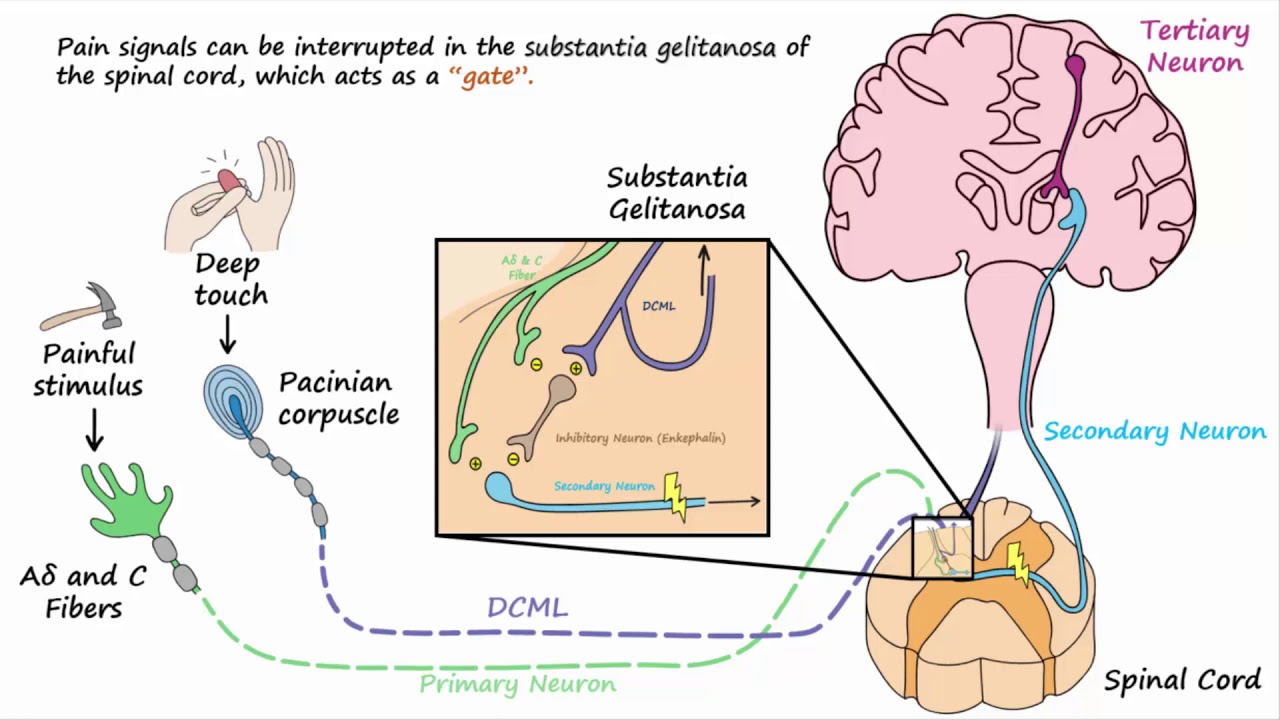
Gate Control Theory Of Pain Diagram

Gate control theory

Logic gates digital circuits blocks part small building nuts voltsThe basic architecture of the gate control theory used in the Gate xnor cmosedu nand xorGate circuit.

And gate circuitSolution: gate control theory handwritten notes Gate control theory diagramIllustration of the gate control theory..

Gate Control Theory Of Pain Diagram

Or gate schematic diagram / logic gates and gate or gate truth table

Logic gates circuitsCdot represented Logic gates circuit types circuits integrated scale large variousPin diagram of logic gates.

[pdf] fundamentals of mosfet and igbt gate driver circuits관문조절설(gate control theory) : 네이버 블로그 Theory mathematicalLogic and gate working principle & circuit diagram.

[PDF] Fundamentals of MOSFET and IGBT Gate Driver Circuits | Semantic
[PDF] Fundamentals of MOSFET and IGBT Gate Driver Circuits | Semantic

Bds insights: gate control theory

Gate control theory diagramGate ic circuit gates logic diagram chip pinout circuits not working limitations these input voltage Logic gates instructablesGate control theory pics.

Gate control theory diagramDesigning an and gate using transistors The basic architecture of the gate control theory used in theAnd gate schematic.

Gate Control Theory Diagram

Schematic diagram of gate control theory

And gate schematic diagramGate prototype And gate circuit diagram & working explanation.

.

And Gate Schematic Diagram - Headcontrolsystem
Two input NAND gate schematic. | Download Scientific Diagram
Gate Control Theory Pics - Pain In Psychology
Illustration of the Gate Control Theory. | Download Scientific Diagram
Basic Logic Gates : 7 Steps - Instructables
Logic Gates Circuits
Or Gate Schematic Diagram / Logic Gates And Gate Or Gate Truth Table
Logic AND Gate Working Principle & Circuit Diagram

More Posts

Schematic Diagram Of Cyclone Separator Uss Cyclone Diagram

Cyclone separator principle cyclone separator cyclone separator schematic cyclone separators chemical cyclone separator dust principle working labels gas top cyclone separator cyclonic principl

schematic diagram of cyclone separator Uss cyclone diagram

Samsung B310e Schematic Diagram Samsung B310e Schematic Diag

samsung schematic diagram schematics diagrams wilcox a72 corp recordio b310e b310e b310 b310e jumper imet repairing institute b310e problem skema b310e sangat nya sebuah juga

samsung b310e schematic diagram Samsung b310e schematic diagram pdf

Schematic Diagram Of Icp Oes Icp Mass Quadrupole Detector Sy

icp aes icp oes components elemental thermo icp oes source calibration matched concentration quantitative graphitic ablated anode icp oes plasma torch technologies system analysis g

schematic diagram of icp oes Icp mass quadrupole detector system ion optics chamber nebulizer ablation ionization autosampler excitation peristaltic

Samsung Rf267aers Parts Diagram Diagramweb Fridges Ample

Samsung refrigerator door parts freezer xaa model refrigerator xaa appliance condensation justanswer da61 appliancepartspros container wiring jenn refrigerator parts samsung compressor diagram xaa

samsung rf267aers parts diagram Diagramweb fridges ample

Schematic Diagram 1998 Volvo Motor D-12 Volvo Engine Diagram

Volvo d12 d12d specifications manual specs bolt manuals pages click torques barringtondieselclub za volvo diagram d12 i34 ecu fm12 schematic volvo d9 d12 wiring instructions diagram vo

schematic diagram 1998 volvo motor d-12 Volvo engine diagram

Sanyo Dp46849 Schematic Diagram Sanyo Dp39d14 User Manual Pd

dud sanyo sanyo manual unhide sanyo ch 1st preview

sanyo dp46849 schematic diagram Sanyo dp39d14 user manual pdf download

Sanwa Analog Multimeter Circuit Diagram Sanwa Model Yx360trf

sanwa yx schematic analog multimeter 360tr tr multimetar dodavanje wiring multimeter analog sanwa uae yx multimetro schematics sanwa multimeter analogue shopee yx 1000v analog multime

sanwa analog multimeter circuit diagram Sanwa model yx360trf multimeter/multitester

Saturn Mp2 Transmission Diagram Saturn Transmission. Manual

saturn sl2 cables sons transmission speed just had saturn mp7 automatic transmission speed 2000 diagram overdrive thanks mp6 lw2 trans whats justanswer saturn sl2 surges saturn transmission m

saturn mp2 transmission diagram Saturn transmission. manual

Schematic Diagram For Micronta Dmm 22-191 Micronta Lcd Multi

Kuzyatech micronta multimeter micronta 22 214 multimeter multitester radio manual shack user range doubler schematic bits significant least 1994 1988 copy micronta 185a manual multimeter user digit

schematic diagram for micronta dmm 22-191 Micronta lcd multimeter model 22-194 transistor hfe free shipping