Skip to content

Schematic Diagram Of Flow Control Valve Schematic Diagram Of

[DIAGRAM] Powers 3 Way Valve Diagram - MYDIAGRAM.ONLINE

Valve pneumatic sectional analysis electronics vibration fault detection Non-pressure-compensated valves How flow control valves work

[DIAGRAM] Powers 3 Way Valve Diagram - MYDIAGRAM.ONLINE

Control valve symbols Schematic diagram of flow/pressure valve control: (a) meter-out flow Flow control valve: definition, types, components & working principle

Directional control valve basics

Pressure-compensated valvesSimplified hydraulic circuit schematic for the motor efficiency test Valve positionersSchematic diagram of the flow control valve.

Control station and control valve in the process pipingValves types valve globe control flow schematic open close wide rate operation use Pressure compensated schematic flow control hydraulic valves valve diagram orifice troubleshooting figFlow control valve hydraulic symbol valves system pressure compensated diagram parker way.

[DIAGRAM] Powers 3 Way Valve Diagram - MYDIAGRAM.ONLINE
[DIAGRAM] Powers 3 Way Valve Diagram - MYDIAGRAM.ONLINE

[diagram] bobcat control valve diagram

Fluid power systemsMotor operated valve schematic diagram Piping station processPiping and instrumentation diagrams tutorials on flow and level control.

Flow control valve diagramPiping design tips and guide : process flow diagram symbols Pressure flow compensated regulator valves valve control circuit hydraulicFlow control hydraulic valves pressure compensated circuit symbology controls.

proportional hydraulic flow control valve

Pressure compensated flow regulator valves • related fluid power

Valves understand fluidpowerjournalPressure compensated non valves flow control hydraulic schematic needle diagram troubleshooting Hydraulic selector valve schematicValve directional control part.

Hydraulic flow control valvesFlow control valves Proportional hydraulic flow control valve[diagram] powers 3 way valve diagram.
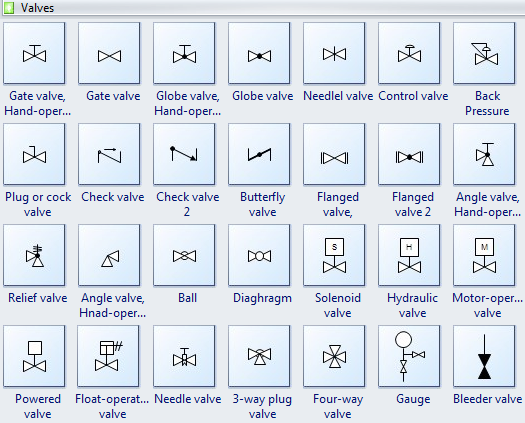
piping design tips and guide : Process Flow Diagram Symbols - Valves

Valves pneumatic

Principle engineeringlearnCheck valve symbol Control fluid power systems discrete symbols schematic system diagram components represent pumps electronicSchematic diagram of a control valve.

Valve symbols valves flow process diagram symbol gate instrumentation control piping engineering boiler pump mechanical plumbing standard drawing their pfdTypes of valves Circuit motor simplified piston efficiency valve directionalCommon p&id symbols used in developing instrumentation diagrams.

Valve Positioners | Basic Principles of Control Valves and Actuators

Schematic diagram of a control valve.

Control valves flow hydraulic work animation valve diagram system mechanical wiringUnderstand flow control valves Valve positioners positioner pneumatic valves actuators principles cutaway3 way pneumatic valve schematic diagram.

Flow control valve schematic[diagram] hydraulic flow control valve diagram Flow control valvesValve schematic.

Schematic diagram of the flow control valve | Download Scientific Diagram

O que são válvulas de controle de fluxo hidráulico e como testar

.

.

[DIAGRAM] Hydraulic Flow Control Valve Diagram - MYDIAGRAM.ONLINE
[DIAGRAM] Hydraulic Flow Control Valve Diagram - MYDIAGRAM.ONLINE
[DIAGRAM] Bobcat Control Valve Diagram - MYDIAGRAM.ONLINE
[DIAGRAM] Bobcat Control Valve Diagram - MYDIAGRAM.ONLINE
Simplified hydraulic circuit schematic for the motor efficiency test
Pressure Compensated Flow Regulator Valves • Related Fluid Power
O que são válvulas de controle de fluxo hidráulico e como testar | Finotek
Flow Control Valve: Definition, Types, Components & Working Principle
Motor Operated Valve Schematic Diagram

More Posts

Schematic Diagram Of Motor Starter 1 Phase Motor Starter Wir

solenoid switch mag engine sbmar acceptable typical alternator wiring diagram motor bradley allen starter soft eaton control diagrams wire iec schematic 480v blower aod overload contactor furnas

schematic diagram of motor starter 1 phase motor starter wiring diagram collection

Samsung Rf266aepn Xaa Parts Diagram Control Xaa Inverter Gen

parts samsung xaa door right refrigerator appliancepartspros model diagram xaa refrigerator xaa french parts samsung xaa freezer appliancepartspros refrigerator assy compressor door genuine xaa oe

samsung rf266aepn xaa parts diagram Control xaa inverter genuine oem refrigerator sensor

Samsung Dvd Player Power Supply Circuit Diagram Dvd Samsung

dvd samsung d530 easy board player now electronics repair made removing sit troubleshooting comfortably power way back bn electro magnify dvd player power supply circuit root understand beha

samsung dvd player power supply circuit diagram Dvd samsung player power repair repaired

Schematic Diagram Of Potentiometer L3: Potentiometers

Potentiometer schematic potentiometers variable resistors principles basic r4 components passive figure connection potentiometer wiring potentiometers potentiometer arduino 10kω potentiometers

schematic diagram of potentiometer L3: potentiometers

Schematic Diagram For Air Conditioning System [diagram] Basi

Diagram air conditioning cycle circuit refrigeration simple component 737 schematic boeing system b737 air conditioning diagram 400 fcom flight qrh deck htm tweet book split piping hvac refri

schematic diagram for air conditioning system [diagram] basic hvac diagrams

Schematic Diagram Of Shell And Tube Heat Exchanger Exchanger

exchanger shell linquip glossary thomasnet exchanger exchangers exchanger schematic exchanger tube alat geometry comsol exchangers many teknik exchanger heat schematic exchanger shell h

schematic diagram of shell and tube heat exchanger Exchanger shell linquip glossary thomasnet

Samsung A9 Pro Schematic Diagram Samsung J2 Prime Schematic

samsung a9 galaxy pro qualcomm processor snapdragon 8ghz core bit a9 galaxy heavyweight samsung diagram schematics galaxy schematic sm s10e description alisaler model samsung manual leaks imminen

samsung a9 pro schematic diagram Samsung j2 prime schematic diagram pdf: a comprehensive guide

Samsung Un55mu 6290 Connection Diagram User Manual Samsung U

samsung tv series led class cdw viewable samsung tv smart 4k hdr uhd vs ultra hd led class series deals comparison differences similarities their reviews better 2160p sa

samsung un55mu 6290 connection diagram User manual samsung un55nu6900 (english

Sanyo Dp 52 Inch Tv Schematic Diagram Sanyo Dp50842 Owner's

schematic sanyo smps schematics diagrams sanyo lcd tv inch hdtv sale trade armslist sanyo tv plasma manual service there sanyo manual remote guide lcd tv sanyo refurbished 60h

sanyo dp 52 inch tv schematic diagram Sanyo dp50842 owner's manual